

Frequently Asked Questions
General
During the winter, the upper soil horizon freezes. This causes a very significant decrease in the soil dielectric constant due to changes in the physical chemistry of the water. Since our sensors measure the dielectric constant, they will see an apparent decrease in volumetric water content.
GroPoint sensors are calibrated to MS soil types, so the decline in measured dielectric may be large enough that readings approach the lower limit of the calibration range.
If you notice sudden spikes in volumetric water content during winter, it is reasonable to infer that water is moving through the soil or that parts of the profile are beginning to thaw.
Yes, you can leave your sensors deployed over the winter. Many customers keep their probes in the ground year round.
Proper installation is critical. If a sensor is installed at an angle or subjected to differential lateral forces during freeze–thaw cycles, cracks can form in the epoxy, which may allow water to reach the electronics.
If you plan to leave probes installed through winter:
- Install the sensors vertically, not bent or at an angle.
- Avoid striking the probe body directly with a hard hammer.
- If driving the sensor is necessary, use a dead blow hammer and follow the recommended installation tools and methods.
The sensors are waterproof and fully potted in epoxy. Problems arise mainly when mechanical stress from improper installation causes cracking.
GroPoint sensors use Time Domain Transmission (TDT) technology, which is based on Time Domain Reflectometry (TDR). TDT measures the transmission time, rather than reflection time, of a pulse along a looped or closed circuit.
In practice, TDT measures the time an electromagnetic wave takes to propagate along a transmission line in the soil. Higher moisture content slows the signal down. Because TDT is a refined form of TDR, it generally offers higher accuracy and lower power consumption than traditional TDR sensors.
Another advantage of TDT over methods such as FDR (frequency domain reflectance) is the measurement bandwidth. TDT operates at a higher bandwidth, which makes it less susceptible to conductivity effects that can introduce noise into capacitance-based measurements.
Our sensors are designed to send about 400,000 pulses in 100 milliseconds. Each measurement is the result of averaging these 400,000 pulses up and down the probe segment, which provides excellent repeatability and accuracy.
What is a true profiling sensor?
Within the world of soil moisture sensors, there are generally three types of soil moisture sensor geometries used to measure soil moisture profile.

To measure soil moisture throughout the full soil horizon, one proven and patented approach is the GroPoint Profile soil moisture probe using TDT⁵ technology. GroPoint Profile uses modular segments that form a single antenna, which provides continuous measurement across the entire length of the sensor rather than only at discrete points.
This continuous averaging across each 15 cm (6 in) segment lets you see a true soil moisture profile and water movement through the soil, instead of leaving gaps between measurement locations.
This is a heavily debated topic in the scientific community. GroPoint sensors are not temperature compensated onboard. Instead, we allow users to apply any corrections offboard as needed.
We have discussed this extensively with soil scientists. Our conclusion is that soil porosity, texture, salinity, and other local conditions often have more influence on accuracy than a generic temperature compensation curve.
In many real deployments, a single probe passes through several soil horizons. Each horizon would need a different temperature compensation. Rather than applying a single built-in correction that may not be appropriate, we recommend letting the scientist or agronomist apply corrections tailored to their specific environment and soil model.
We do not recommend field recalibration. If recalibration is ever required, probes should be returned to us. The calibration solutions we use are difficult to transport and the software used for calibration requires specialized training.
From our lab tests, we have not observed substantial drift in calibration accuracy over time. Any drift that does occur remains within the original accuracy specification of the probes.
The long-term stability is due to the way the probe is constructed and the aging characteristics of the measuring components, which are designed to have minimal change under normal operating conditions.
GroPoint sensors operate reliably from 6.0 V to 18 V. They may still function down to around 5.0 V, but measurement errors can start to appear once the supply drops near 5.5 V.
Because we do not characterize accuracy below 6.0 V, we recommend designing your system so that the sensor supply never falls below 6.0 V during operation.
Battery life depends on three main factors:
- The number of sensors connected to the logger.
- The measurement interval (how often you log data).
- The operating temperature and battery type.
The graph below shows a conservative estimate of deployment life based on the number of sensors and the sampling interval at 20 °C.

Our standard Bluetooth data logger battery is rated for a discharge temperature range from about -55 °C to +85 °C. At extreme temperatures, different batteries may be required to maintain the necessary voltage, especially when powering higher sensor loads.
GroPoint Profile
Is the GroPoint Profile compatible with all data loggers?
GroPoint Profile will work with virtually any data logger that supports the SDI-12 standard.
How do the new GroPoint Profile S-T-x probes differ from the N-T-x probes?
- Most S-T-x sensors have fewer soil temperature sensors at lower depths (segments 3 or 4 and lower).
- Even better moisture sensor stability over temperature.
- Firmware updates for debugging sensor issues.
- Bootloader support to allow firmware to be updated with new features or fixes.
Can the GroPoint Profile be used as a portable solution?
GroPoint Profile is for permanent or semipermanent installations only. The soil moisture probe should not be briefly placed in the ground to ensure proper accuracy. It performs best and with the highest soil moisture accuracy when the soil has fully settled around the probe. However, given the ease of installing (no excavation required, no access tube required) and its low price point relative to other soil profiling sensors, there is little reason not to use permanent GroPoint Profile installations to monitor soil moisture throughout your site.
I am not in BC or Canada. Can I buy and obtain support for GroPoint products locally?
GroPoint has dealers in several international locations. You can find your local dealer on the
Dealers page.
GroPoint soil probes and data loggers are also sold online and we offer several self-help support resources, as well as unlimited support via phone, email and online chat.
What is the area of influence, or measurement volume, of the GroPoint Profile?
GroPoint Profile detects water as much as 5 cm (2 inches) from the surface of the probe fins and 2 L volume of influence per 15 cm segment. Like all dielectric based sensors, moisture closest to the surface of the soil moisture probe has more influence on the readings than moisture further away, so soil closely surrounding the sensor will have a greater influence on the soil moisture reading than soil further away.
What measurement frequency do GroPoint soil moisture sensors operate at?
The GroPoint Lite family of sensors sends TDT pulses with sub nanosecond rise times, around 500 ps, so the frequency bandwidth exceeds 1–2 GHz.
What does my sensor's ID string mean?
Example: 013RIOTTECHGPLPTS036SN612345
Pattern: allccccccccmmmmmmvvvxxxxxxxx
Where:
a = sensor address (0)
ll = SDI-12 compatibility (13 for V1.3)
cccccccc = company name (RIOTTECH)
mmmmmm = sensor model number (GPLPTS)
vvv = sensor version (036)
xxxxxxxx = serial number (SN612345)
How do I switch my SDI-12 GroPoint Profile sensor to Modbus?
Warning: In rare cases, if this process is not done properly, you can permanently disable your sensor and it will no longer be usable. If this occurs your sensor will not be covered under warranty.
Before beginning, ensure that the cable attached to your GPLP sensor has 5 conductors. If you switch your sensor without all wires present, you will not be able to communicate with your sensor anymore.
Required: You will need an SDI-12 interface where you can send transparent SDI-12 commands to your sensor, a Modbus/RS-485 interface to communicate once you have switched, and software for both interface types (for example GP Reader PC).
The extended command to switch from SDI-12 to MODBUS (assuming the sensor has the factory default address of 0) is:
0Xss=00020000!
If the command is correctly formatted and recognized the sensor will respond with: 0ss: OK.
If you do not see the 0ss: OK message then you should check the sensor address and try again.
Power cycle your sensor and it will be in Modbus mode. If the command was unsuccessful, the sensor will remain in SDI-12.
How do I switch my MODBUS GroPoint Profile Probe to SDI-12?
Warning: In rare cases, if this process is not done properly, you can brick your sensor and it will no longer be usable. If this occurs your sensor will not be covered under warranty.
Required: a MODBUS/RS-485 interface, an SDI-12 interface and software for both interface types (for example GP Reader PC).
Before beginning, make sure the SDI-12 wire is accessible (this wire color can change depending on the cable, please reference your wiring document).
Follow example below for a sensor with MODBUS address 0x01, if your address is different be sure to change it in the command. Bold is the command sent, non-bold is sensor response, last two bytes are CRC bytes.
1. First confirm that the sensor is communicating by requesting the sensor's ID string:
01 11 C0 2C
01 11 1B 31 33 52 49 4F 54 54 45 43 48 47 50 4C 50 54 53 30 33 36 53 4E 34 30 30 35 34 34 FF AD 9D
Received Server ID: 13RIOTTECHGPLPTS036SN400544
2. Disable write protect. This involves a single register write command (06) to the holding register with offset 0xB9CD. The value written must be 0x4B36 to disable write protection (any other value leaves write protection enabled).
01 06 B9 CD 4B 36 8B 8F
01 06 B9 CD 4B 36 8B 8F
3. Use the special user defined function code 73 (hexadecimal 0x49) to switch the sensor operating mode to 0x00 (for SDI-12 communications). The sensor responds with an exception response (most significant bit of command byte set) and the acknowledgement code 0x05 to indicate successful execution of the command (again, last two bytes are CRC bytes):
01 49 00 17 90
01 C9 05 B6 53
When the sensor is power cycled it will start up in the SDI-12 communication mode. It should have the factory default SDI-12 address of "0".
What power-on delay time is needed for GroPoint SDI-12 sensors?
GroPoint Profile sensors need a minimum power-on delay of 350 ms before they will respond to a command.
What are GroPoint sensor's default MODBUS communication settings?
Our sensors' default MODBUS settings are baud rate of 19200, even parity, 8 data bits and 1 stop bit.
Does the RS485 protocol use Modbus RTU to connect to sensors?
Yes, the GroPoint Profile can be configured for Modbus over RS-485 and SDI-12 over RS485.
What is the MODBUS measurement command structure?
The MODBUS measurement command for the sensor requires two steps:
- Trigger measurement: The first command triggers the moisture measurement, which prompts the sensor to return an acknowledgement.
- Retrieve measurement results: After a brief delay, a second command is sent to obtain the actual measurement results.
For detailed instructions on the MODBUS measurement sequence, refer to Appendix D in the GroPoint Profile manual.
Can you power GroPoint Profile probes with a continuous 12 VDC?
Yes, there is no problem continuously powering the sensors with 12 V.
What are GroPoint Profile sensors' SDI-12/RS-485 communication settings?
The SDI-12 over RS485 communications parameters are 9600 baud, no parity, 8 data bits and 1 stop bit. The SDI-12 over RS485 sensor communications replaces the normal SDI-12 break signal with a framing character. All commands to the sensor must be preceded by the framing character. The default framing character is "@" but can be changed to a different character by using the extended command aXFc! where c is the desired framing character.
Does temperature come standard with the GroPoint Profile?
Yes, the standard configuration for GroPoint Profile is with temperature sensing capabilities. However, the GroPoint Profile comes in two versions: Volumetric Soil Water Content and Soil Temperature Sensing or Volumetric Soil Water Content Sensing. Please specify which configuration suits your needs when placing an order.
How long does it take for my SDI-12 GroPoint sensor to complete a measurement?
All sensors require a minimum 350 ms power-on delay time. After that, the time it takes to complete measurements depends on the length of your GroPoint Profile probe:
2-segment: 1.4 s
3-segment: 1.6 s
4-segment: 2.0 s
5-segment: 2.1 s
6-segment: 2.6 s
8-segment: 3.6 s
Note: all values determined with GroPoint Bluetooth Datalogger. Other SDI-12 loggers' measurement times may vary.
What does a -88.8 temperature reading mean?
-88.8 means there was a failure with that temperature sensor on the GPLP Profile Probe, or that the temperature sensor is not present on the board if you request more temperature registers than are present on your MODBUS sensor.
What does a -99.9 reading mean?
-99.9 means there is an internal inter board communication issue. Please contact support@gropoint.com for assistance.
Can damage to the housing affect my moisture readings?
Minor cosmetic damage to the polycarbonate housing will not impact soil moisture or temperature readings. However, significant damage, such as cracks or gouges, can interfere with moisture measurements. This is because larger damage reduces the material between the soil and sensing element, and can allow water to infiltrate between the housing and the epoxy encapsulating the sensor. For this reason, proper installation and extraction methods are essential to prevent housing damage.
Are GroPoint sensors affected by changes in temperature?
GroPoint sensors are minimally impacted by temperature changes, so you should not see significant variations in moisture readings due to temperature shifts affecting the sensor's measuring circuit. However, be aware that the dielectric constants of water and different soil types can vary with temperature, which may influence moisture content readings under certain conditions.
How do I validate the readings from my GroPoint sensor?
Validation depends on whether the sensor is installed and your desired accuracy level.
Before installation:
- Hand Grab Method (Least Accurate): Take readings while holding a sensor segment. Readings will fluctuate based on hand size and contact. Expect increases up to 20% or more. You can use a damp towel but ensure that it is thick enough and covering enough of the sensor body. Damp paper towel is not sufficient to get a reading.
- Water Immersion Method: Immerse the sensor in a large water container (minimum 15 cm diameter). Readings increase segment by segment with immersion, reaching a maximum around 55–60% VMC.
- Sand Column Method (Most Accurate): Install the sensor in a capped PVC/ABS pipe (minimum 8 cm inner diameter). Fill with sand, tamp, and saturate with water. Readings should stabilize around 33% VMC, though results may vary depending on sand type and compaction.
After installation:
- Water Pour Test: Pour a large bucket of water slowly around the probe's insertion point while monitoring readings. They should rise steadily, reflecting soil porosity, with segment readings increasing sequentially.
- Troubleshooting low readings: Rapid spikes followed by a rapid drop suggest air gaps around the sensor.
Consistently low readings could indicate the presence of rocks, stones, roots or other underground objects near the sensor body.
How do I interpret my sensor readings?
GroPoint soil moisture sensors measure in % Volumetric Moisture Content (%VMC), which represents the percentage of water volume in the soil. The interpretation of moisture values depends on several factors, specifically soil type and its water holding characteristics, and your crop type. Different soil types have distinct wilting points, field capacities and saturation points.
- Wilting point: The soil moisture level at which plants can no longer extract water.
- Field capacity: The amount of soil moisture retained after excess water has drained away.
- Saturation: The maximum amount of water the soil can hold.
To understand what your sensor readings mean for you, you should know roughly what your soil type is. This allows you to know whether your moisture content is in an acceptable range. For example, sandy loam soils have a field capacity of approximately 21% VMC whereas sandy clay soils have a field capacity of approximately 33% VMC.
Different crops require a certain field capacity for optimal growing conditions. If you know your soil type and crop type, then you can figure out your optimal soil moisture range.
Can you explain your calibration process for the GroPoint Profile?
Our calibration process is extensive, involving multiple reference solutions with different dielectric constants in 6 inch diameter columns. Each segment is individually calibrated to match a reference percent moisture content. The process is time consuming but very accurate, and very repeatable against a reference.
Does it need to be calibrated for different soil types?
GroPoint soil probes are factory calibrated for use in most soils and deliver optimal accuracy within 8–41% volumetric moisture content (VMC). There are also two other standard calibrations that can be used, which you can specify when you order.
Below is an image of a standard soil texture triangle. By default, calibration is done for a wide variety of soil types represented by the Red area. You can also request that your sensor is calibrated for clay or highly saline soil (the Green area) or sandy soils (Blue).
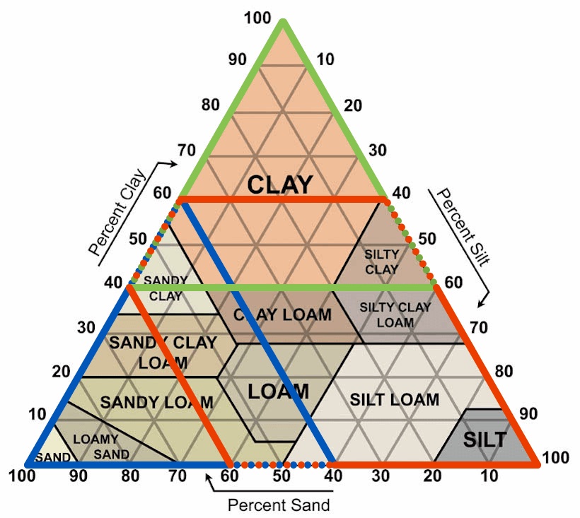
For specific soil types, end customers can also perform their own custom calibration (see Appendix C of the
GroPoint Profile User Manual).
While the absolute VMC values may vary due to differences in soil composition, the relative changes detected by the sensor remain consistent across all soil types. For instance, a 5% VMC increase measured in sandy soil will correspond to a 5% change in clay, allowing for reliable tracking of moisture fluctuations regardless of soil type.
If I use a sensor calibrated for a different type of soil than I have, will I lose accuracy?
If you are using a sensor with the wrong calibration, measurements will have a small absolute error and may read either too high or too low by up to 4%.
Can soil specific calibrations be done?
RioT does not perform soil specific calibrations, but customers can carry these out if desired. If the soil type is known, users can apply a third order polynomial adjustment to the sensor's calibration coefficients to create a soil specific calibration. For details on this process, refer to Appendix C of the
GPLP manual.
Alternatively, general corrections can be applied if you have sandy soil or clay/high salinity soil (contact support@gropoint.com). Users can also adjust sensor data for soil conditions post measurement using software like Excel.
My soil horizons span sandy, loamy and clay mixtures. Can each segment be calibrated differently to more accurately measure the different soil horizons?
Yes. Each segment can be calibrated for different soil horizons via SDI-12 extended commands entered through a small software utility.
What is TDT5? How does it differ from other soil measurement methods?
TDT5 is a proprietary technology based on Time Domain Transmission (TDT), which is a refined version of Time Domain Reflectometry (TDR). TDT measures the time taken for an electromagnetic wave to propagate along a given length of a transmission line in the soil. Moisture in the soil changes the soil's dielectric properties, so the electromagnetic wave travels at different rates in wet soil compared to dry soil. This allows for the accurate determination of soil moisture content.
However, we add our own engineering designs that result in a less expensive, more robust and more accurate (with greater repeatability) sensor than with pure TDT alone. This enhances TDT in five (hence "TDT5") key ways:
- Measures with an antenna 5 times longer than the physical length of the probe, which reduces the impact of noise and provides an average across the entire length of each segment of the probe.
- Filters 400,000 pulses for each measurement which boosts accuracy to ±2% and repeatability to less than 0.2%.
- Captures measurement in less than 100 ms, which reduces power consumption.
- Embeds antenna and circuitry on a single board, which dramatically reduces cost to manufacture.
- Encases the entire sensor in a durable, sealed polycarbonate housing, which maximizes durability.
Learn more about TDT5 here.
What is the difference between TDT and capacitance methodologies for measuring soil moisture? Are there any distinct advantages of TDT over capacitance?
Capacitance probes set up an oscillating circuit that has a different frequency of oscillation depending on the moisture content, whereas TDT (Time Domain Transmission) measures the time taken for an electromagnetic wave to travel along a given length of a transmission line in the soil. Both are affected by the soil's dielectric properties, so the frequency of oscillation (capacitance) or the travel time (TDT) is related to the moisture content.
One of the drawbacks of the capacitance method is that the frequencies involved are usually fairly low (less than 500 kHz). If they were higher, the current consumption (which is directly related to frequency, that is, higher frequency means higher current) would be fairly high. The issue is that at these relatively low frequencies the measurement is quite negatively affected by conductivity, which leads to a lot of variability in the readings (poor accuracy). TDT frequency bandwidths are much higher, on the order of 500 MHz and up. Therefore they are not nearly as susceptible to electrical conductivity.
An advantage of TDT is that antennas can be constructed that measure the soil moisture over a large area. This is exactly what permits the GroPoint Profile to measure soil moisture over the entire length of the probe, averaging each 15 cm (6 inch) segment. Capacitance probes, because of their physical construction, will only provide point measurements (measuring only at the point where sensors are located).
Are there any environments or soil types I should avoid with my GroPoint sensors?
GroPoint sensors are designed for inorganic soils that become saturated around 45% VMC. The sensors' accuracy starts to decline for moisture contents above 41% and has a max reading around 55–60% VMC.
Environments that become saturated higher than this or that are very porous with air gaps are less ideal applications for GroPoint sensors. Such environments might include:
- Composts with larger particulate
- Rice paddy fields
- Very high salinity
- Peat
- Wetlands
If you are unsure whether your environment is suitable, contact sales@gropoint.com for advice.
Why are my sensor readings not as expected?
Unexpected sensor readings can result from several factors:
- Installation settling period: It can take several weeks for a sensor to provide accurate readings, depending on how it was installed and the level of soil disruption. To check soil contact, pour water over the sensor. If moisture readings spike quickly to 40–50%, this may indicate air gaps, and the soil might need more time to settle around the sensor.
- Soil type variability: Different soil types can impact sensor accuracy. Calibration adjustments may be necessary to account for variations in soil composition. This can be done in the sensor using custom soil calibration (see Appendix C of the GroPoint Profile manual) or in post processing.
- Obstructions in the measuring field: Rocks, large roots, or any object within six inches of the sensor can interfere with readings by affecting the moisture levels in the sensor's field of influence. If you suspect there may be large roots or you have rocky soil, you can try moving your sensor to a new location.
- Improper installation: Installation errors can create air pockets around the sensor, causing water to flow around rather than through the soil, leading to irregular readings. Review proper sensor installation techniques for assistance.
- Sensor malfunction: In rare cases, if the readings seem unrealistic or the sensor fails to respond to changes in moisture levels, there may be a technical issue. If this occurs, contact support at support@gropoint.com.
What should I do if my sensor is not communicating, or the communication is intermittent?
- Check sensor connections: Ensure the sensor is securely connected to your data logging equipment. Verify that all wires are properly connected and, if a connector is used, make sure no wires have come loose.
- Inspect the sensor cable: Look for any damage to the cable, which could be caused by rodent activity or general wear.
- Verify connector wiring: If a connector is attached, confirm that the wiring is correct.
- Ensure proper wiring to data logger: Double check that the sensor is correctly wired to your data logging device according to the equipment's specifications.
- Confirm power supply: Check that your data logger's battery is charged and that the sensor is receiving a consistent 12 V power supply. When the sensor starts a measurement, a brief current spike occurs. If the power supply or connection cannot handle this current spike, the sensor supply voltage may drop low enough to cause the sensor to reset. If this happens, only the sensor address will be returned for the D0! get data command, without any data.
- Verify sensor address: Make sure you are using the correct address for commands. Sensors are shipped with a default address of 0. Use the ?! command to determine a sensor's address (this can only be sent when there is just a single sensor connected).
- Set unique addresses for multiple sensors: If you have multiple sensors connected, you must ensure each sensor has a unique address to avoid communication conflicts.
- Send SDI-12 commands manually: To test communication, send the command aI! (where a is the sensor address). If the sensor is communicating, it will return an ID string similar to 013RIOTTECHGPLPTS035SN600000.
- Contact support if needed: If issues persist, reach out to support at support@gropoint.com for further assistance.
Why is proper sensor installation important?
Proper installation is crucial for several reasons:
- Reduces risk of damage: Proper techniques help prevent damage to the sensor, especially with longer probes. Damage caused to the sensor during installation is not covered under warranty.
- Minimizes soil disturbance: Careful installation minimizes disruption to the surrounding soil, preserving natural conditions.
- Prevents mixing of soil layers: Proper installation avoids unintentional mixing of soil layers, which could affect sensor readings.
- Preserves soil structure and water flow: Maintaining the natural soil structure ensures that moisture moves as it would naturally, allowing for more reliable measurements.
- Speeds up accurate operation: With correct installation, the sensor reaches stable, accurate readings more quickly.
How do I properly install my GroPoint Profile Probe?
For proper installation and best practices, we suggest using the GroPoint installation kit which includes a pilot rod that matches the profile of the sensor body and a slide hammer attachment. Read Appendix A of the
GroPoint Profile manual and watch the installation video on our website. Some installation best practices are:
- Pilot hole preparation: Ensure the pilot hole is the correct depth and properly formed before inserting the sensor. The pilot rod should remain vertical both while making the pilot hole, and when removing the pilot rod, to avoid overly enlarging the hole.
- Timing: Insert the sensor as soon as possible after removing the pilot rod to prevent the hole from collapsing, particularly in clay soils.
- Lubrication: Use water poured along the sensor body during installation to help with insertion.
- Gentle tapping: Only use a dead blow hammer, applying many light taps to the cap instead of hard blows to prevent damage. Tuck the cable into the notch in the cap to avoid damage to it.
- Light soil tamping: After installing the sensor to the correct depth, you can tamp the soil around the sensor body to encourage it to form around the sensor. Be cautious to not over tamp, as this could damage the sensor or compact the soil beyond its natural compaction.
- Patience: Sensor installation can take time, particularly in challenging soil conditions. It requires patience to ensure proper insertion without damage.
- Distance: The profile probe should be at least 6 inches away from any object to avoid them being in the sensing field of influence.
How do I properly remove my GroPoint Profile Probe from the ground?
To safely remove your GroPoint Profile Probe, avoid pulling from the cable or cap, as this could detach the cable from the electronics or pull the cap off the sensor housing. Begin by digging around the sensor to expose enough of the blue housing for a secure grip. Once you have a firm hold on the housing, pull the sensor straight up. It is important not to twist or bend the sensor during this process, as doing so could cause damage.
How deep in the soil should the GroPoint Profile be placed?
These sensors are intended to have the top of the probe near the surface of the soil, with the length of the probe determining the lowest depth of the soil moisture and temperature points.
How does soil disturbance affect soil moisture measurements?
Soil disturbance, such as compaction or mixing of soil layers, alters natural soil properties like structure and porosity. This can skew soil moisture data by changing how water moves through and is retained by the soil. In disturbed soils, water may either infiltrate too quickly or be blocked from reaching deeper layers, leading to inaccurate readings.
What is the impact of soil compaction on soil moisture?
Compacted soil has reduced air filled pore spaces, which limits water infiltration and retention. This can result in lower accuracy of moisture measurements since the soil may hold less water than it would in its natural, undisturbed state. Compaction can also impede root growth and nutrient cycling, further altering moisture dynamics.
How does mixing soil horizons affect moisture readings?
When soil horizons (layers) are mixed during installation, it changes the natural arrangement of soil textures (for example sandy versus clayey layers), which can impact how water moves through the soil. This mixing can cause sensors to record inaccurate moisture levels because the hydraulic properties of the soil are altered.
Why is it important to minimize soil disturbance during sensor installation?
Minimizing soil disturbance ensures that moisture readings reflect the natural soil environment. Disturbances like bore holes or improper repacking of soil around sensors can create air pockets or preferential water pathways, leading to false moisture readings. Using the GroPoint pilot rod can help mitigate these effects because it matches the sensor's profile for minimal soil disruption.
After inserting the GroPoint Profile into the hole created by the pilot rod, will there be any air gaps between the soil and the probe that will affect the accuracy?
The pilot rod is specially designed and manufactured to create a pilot hole that exactly matches the dimensions of the GroPoint Profile. During installation, it is important that the pilot rod installation is done properly and that the pilot rod is inserted vertically using the slide hammer and that the pilot rod is not tilted back and forth. When the proper installation process is followed carefully, there will be very good soil contact and no air gaps.
In the event of an improper installation, where the pilot rod is moved side to side during hammering, the pilot hole will be too large (larger near the top than at the bottom), and those gaps will take some time to close. The soil will take a few days to a week to fully settle back and seal 100% against the probe surface. You could also create a soil slurry at the surface to correct for improper installation.
Will I really be able to drive the pilot rod into hard, dry, compacted clay soils with the slide hammer? And even if I do, are you sure I will be able to get it out again?
Since the slide hammer provides weight for insertion and extraction, installing even a long (5 or 6 segment) GroPoint Profile into hard clay soils is not a problem. It is laborious, but the slide hammer does most of the work for you. The upward swing carries with it the momentum of the slide hammer's weight, and as such the pilot rod does work its way out. We have deployed in many clay soils. Our GroPoint Profile installation tutorial video was shot in a region with fairly hard clay soil. You will see that the pilot rod seems to go in and come out effortlessly (although it was not completely without effort).
The slide hammer is quite expensive to ship to the US from Canada. Can I purchase it from and ship it within the US?
Our longtime partner, and the manufacturer of the slide hammer, AMS (based in Idaho), sells it on their website. Here is a link to the
product page.
How should I store my installation kit?
After using the pilot rod for installation, clean off excess dirt and moisture before storing. If the pilot rod is stored wet, it can rust which may lead to the threads for the slide hammer no longer being functional.
What is the maximum length of cable that can be used with the sensor?
For SDI-12 sensors, according to the
SDI-12 specification, the combined length of all sensors connected to a data logger cannot exceed 610 m (2,000 feet). This can be one sensor with a 610 m cable or 10 sensors each with a 61 m cable.
For analog sensors, the maximum length is 305 m (1,000 feet).
It should be noted that the longer the cable is, the more susceptible the sensor is to catastrophic damage or failure due to increased voltage spikes from lightning strikes. A long cable becomes a very large antenna to amplify the voltage. Cable should be buried wherever possible.
The minimum wire gauge when using a cable approaching the maximum should be 20 AWG.
If you are interested in getting rid of the cable, check out this link: https://www.gropoint.com/products/wireless.
Can the sensor cable be buried, and is it durable enough to be left exposed on the surface of the ground?
GroPoint sensors are furnished with a high quality cable suitable for direct burial or exposure to direct sunlight. It is resistant to damage from insects, abrasion and normal environmental exposure. However, mechanical damage from hoes, coyotes, gophers, other animals, and cultivators can easily cut this cable. Any problem with this sensor will most likely be due to damage to the electrical cable. To prevent damage, it is strongly recommended that the cable be installed in 3/4 inch electrical conduit. This size conduit is required to accommodate the passage of the plug connector.
Do GroPoint probes need to be removed during winter?
GroPoint sensors do not need to be removed from the ground during winter. However, it is recommended to protect the cables from potential damage by rodents and other animals during this time.
How does the GroPoint Profile probe hold up to chemicals in the soil or different pH levels?
GroPoint sensor housings are made of polycarbonate with glass filled ABS tip and cap. Both materials are resistant to a wide range of chemicals found in organic soils, acids and bases. If you are concerned whether the sensor integrity will hold in your environment, check the chemical compatibility charts for polycarbonate and ABS.
GroPoint Lite
SDI-12
General
Are GroPoint Lite soil sensors compatible with all data loggers?
GroPoint Lite will work with virtually any data logger. Just ensure your data logger will handle the output of your
GroPoint Lite sensor whether it's SDI-12, RS-485, 0–5 mA or 4–20 mA. If you are looking for a datalogger, check out
GP-BTDL Bluetooth SDI-12 Data Logger
.
Can a GroPoint Lite soil sensor be used as a portable solution?
No, GroPoint soil moisture sensors are meant to be used on a permanent or semi-permanent basis. There should be minimal
disturbance of the surrounding soil for proper accuracy.
What is the area of influence, or measurement volume, for the sensor?
The GroPoint Lite measures the average volumetric water content along its active length, about 15 cm (6″), which is
3 cm (1.25″) from the top and 2.5 cm (1″) from the bottom of the sensor, whether the sensor is installed vertically
or horizontally. Under most conditions, the sensor’s active range extends about 10 cm (4″) out from the side of the
sensor, and 2.5 cm (1″) from the tip.
I’m not in BC or Canada. Can I buy and obtain support for GroPoint products locally?
GroPoint has dealers in several international locations. You can find your local dealer on the
Dealers page.
GroPoint soil probes and data loggers are also sold online and we offer several self-help support resources, as well
as unlimited support via phone, email and online chat.
What measurement frequency do GroPoint soil moisture sensors operate at?
The GroPoint Lite family of sensors sends TDT pulses with sub nanosecond rise times, around 500 ps, so the frequency
bandwidth exceeds 1–2 GHz.
What does my sensor's ID string mean?
013RIOTTECHGPLPTS036SN612345
allccccccccmmmmmmvvvxxxxxxxx
Where:
a = sensor address (0)
ll = SDI-12 compatibility (13 for V1.3)
cccccccc = company name (RIOTTECH)
mmmmmm = sensor model number (GPLPTS)
vvv = sensor version (036)
xxxxxxxx = serial number (SN612345)
Communication & Configuration
What power-on delay time is needed for GroPoint SDI-12 sensors?
GroPoint Lite sensors need a minimum power-on delay of 350 ms before they will respond to a command.
Can you power GroPoint Lite SDI-12 sensors with a continuous 12 VDC?
Yes, there is no problem continuously powering the sensors with 12 V.
Does temperature come standard with the GroPoint Lite SDI-12 sensors?
Yes, the standard configuration for GroPoint Lite is with temperature sensing capabilities.
Sensor Readings
Can damage to the housing affect my moisture readings?
Minor cosmetic damage to the polycarbonate housing will not impact soil moisture or temperature readings. However,
significant damage, such as cracks or gouges, can interfere with moisture measurements. This is because larger damage
reduces the material between the soil and sensing element, and can allow water to infiltrate between the housing and
the epoxy encapsulating the sensor. For this reason, proper installation and extraction methods are essential to
prevent housing damage.
Are GroPoint sensors affected by changes in temperature?
GroPoint sensors are minimally impacted by temperature changes, so you should not see significant variations in moisture
readings due to temperature shifts affecting the sensor’s measuring circuit. However, be aware that the dielectric
constants of water and different soil types can vary with temperature, which may influence moisture content readings
under certain conditions.
How do I validate the readings from my GroPoint sensor?
Validation depends on whether the sensor is installed and your desired accuracy level.
Before installation:
- Hand Grab Method (Least Accurate): Take readings while holding a sensor segment. Readings will fluctuate based on hand size and contact. Expect increases up to 20% or more. You can use a damp towel but ensure that it is thick enough and covering enough of the sensor body. Damp paper towel is not sufficient to get a reading.
- Water Immersion Method: Immerse the sensor in a large water container (minimum 15 cm diameter). Readings increase segment by segment with immersion, reaching a maximum around 55–60% VMC.
- Sand Column Method (Most Accurate): Install the sensor in a capped PVC/ABS pipe (minimum 8 cm inner diameter). Fill with sand, tamp, and saturate with water. Readings should stabilize around 33% VMC, though results may vary depending on sand type and compaction.
After installation:
- Water Pour Test: Pour a large bucket of water slowly around the probe's insertion point while monitoring readings. They should rise steadily, reflecting soil porosity, with segment readings increasing sequentially.
- Troubleshooting low readings: Rapid spikes followed by a rapid drop suggest air gaps around the sensor. Consistently low readings could indicate the presence of rocks, stones, roots or other underground objects near the sensor body.
How do I interpret my sensor readings?
GroPoint soil moisture sensors measure in % Volumetric Moisture Content (%VMC), which represents the percentage of
water volume in the soil. The interpretation of moisture values depends on several factors but specifically soil type
and its water-holding characteristics, and your crop type. Different soil types have distinct wilting points, field
capacities and saturation points.
Wilting point: The soil moisture level at which plants can no longer extract water.
Field capacity: The amount of soil moisture retained after excess water has drained away.
Saturation: The maximum amount of water the soil can hold.
To understand what your sensor readings mean for you, you should know roughly what your soil type is. This allows you
to know whether your moisture content is in an acceptable range. For example, sandy loam soils have a field capacity
of approximately 21% VMC whereas sandy clay soils have a field capacity of approximately 33% VMC.
Different crops require a certain field capacity for optimal growing conditions. If you know your soil type and crop
type, then you can figure out your optimal soil moisture range.
Calibration & Accuracy
Can you explain your calibration process for the GroPoint Lites?
Our calibration process is extensive, involving multiple reference solutions with different dielectric constants in
6 inch diameter columns. Each segment is individually calibrated to match a reference % moisture content. The process
is time consuming but very accurate, and very repeatable against a reference.
Does it need to be calibrated for different soil types?
GroPoint soil probes are factory calibrated for use in most soils and deliver optimal accuracy within 8–41% volumetric
moisture content (VMC). There are also two other standard calibrations that can be used, which you can specify when you
order.
Below is an image of a standard soil texture triangle. By default, calibration is done for a wide variety of soil types represented by the Red area. You can also request that your sensor is calibrated for clay or highly saline soil (the Green area) or sandy soils (Blue).
For specific soil types, end customers can also perform their own custom calibration (see Appendix C of the
GroPoint Profile User Manual
).
While the absolute VMC values may vary due to differences in soil composition, the relative changes detected by the
sensor remain consistent across all soil types. For instance, a 5% VMC increase measured in sandy soil will correspond
to a 5% change in clay, allowing for reliable tracking of moisture fluctuations regardless of soil type.
If I use a sensor calibrated for a different type of soil than I have, will I lose accuracy?
If you are using a sensor with the wrong calibration, measurements will have a small absolute error and may read either
too high or too low by up to 4%.
Can soil specific calibrations be done?
RioT does not perform soil specific calibrations, but customers can carry these out if desired. If the soil type is
known, users can apply a third order polynomial adjustment to the sensor’s calibration coefficients to create a
soil specific calibration. For details on this process, refer to Appendix C of the
GPLP manual
.
Alternatively, general corrections can be applied if you have sandy soil or clay/high salinity soil
(contact support@gropoint.com). Users can also adjust sensor data for soil conditions post measurement using software
like Excel.
My soil horizons span sandy, loamy and clay mixtures. Can each segment be calibrated differently to more accurately
measure the different soil horizons?
Yes. Each segment can be calibrated for different soil horizons via SDI-12 extended commands entered through a small
software utility.
What is TDT 5? How does it differ from other soil measurement methods?
TDT 5 is a proprietary technology based on Time Domain Transmission (TDT), which is a refined version of
Time Domain Reflectometry (TDR). TDT measures the time taken for an electromagnetic wave to propagate (travel) along a
given length of a transmission line in the soil. Moisture in the soil changes the soil’s dielectric properties, so
the electromagnetic wave travels at different rates in wet soil compared to dry soil. This allows for the
accurate determination of soil moisture content. However, we add our own engineering designs that result in a less
expensive, more robust and more accurate (with greater repeatability) sensor than with pure TDT alone. This enhances
TDT in five (hence “TDT 5“) key ways:
- Measures with an antenna 5 times longer than the physical length of the probe, which reduces the impact of noise, and provides an average across the entire length of each segment of the probe.
- Filters 400,000 pulses for each measurement, which boosts accuracy to ±2% and repeatability to < 0.2%.
- Captures measurement in less than 100 ms, which reduces power consumption.
- Embeds antenna and circuitry on a single board, which dramatically reduces cost to manufacture.
- Encases the entire sensor in a durable, sealed polycarbonate housing, which maximizes durability.
Learn more about TDT 5 here .
What is the difference between TDT and capacitance methodologies for measuring soil moisture? Are there any distinct
advantages of TDT over capacitance?
Capacitance probes set up an oscillating circuit that has a different frequency of oscillation depending on the
moisture content, whereas TDT (Time Domain Transmission) measures the time taken for an electromagnetic wave to travel
along a given length of a transmission line in the soil. Both are affected by the soil’s dielectric properties, so the
frequency of oscillation (capacitance) or the travel time (TDT) is related to the moisture content.
One of the drawbacks of the capacitance method is that the frequencies involved are usually fairly low (less than 500 kHz). If they were higher, the current consumption (which is directly related to frequency, that is, higher frequency means higher current) would be fairly high. The issue is that at these relatively low frequencies the measurement is quite negatively affected by conductivity, which leads to a lot of variability in the readings (poor accuracy). TDT frequency bandwidths are much higher, on the order of 500 MHz and up. Therefore they are not nearly as susceptible to electrical conductivity.
An advantage of TDT is that antennas can be constructed that measure the soil moisture over a large area. This is exactly what permits the GroPoint Profile to measure soil moisture over the entire length of the probe, averaging each 15 cm (6″) segment. Capacitance probes, because of their physical construction, will only provide point measurements (measuring only at the point where sensors are located).
Are there any environments or soil types I should avoid with my GroPoint sensors?
GroPoint sensors are designed for inorganic soils that become saturated around 45% VMC. The sensors’ accuracy starts to
decline for moisture contents above 41% and has a max reading around 55–60% VMC.
Environments that become saturated higher than this or that are very porous with air gaps are less ideal applications
for GroPoint sensors. Such environments might include:
- Composts with larger particulate
- Rice paddy fields
- Very high salinity
- Peat
- Wetlands
If you are unsure whether your environment is suitable, contact sales@gropoint.com for advice.
Troubleshooting
Why are my sensor readings not as expected?
Unexpected sensor readings can result from several factors:
- Installation settling period: It can take several weeks for a sensor to provide accurate readings, depending on how it was installed and the level of soil disruption. To check soil contact, pour water over the sensor. If moisture readings spike quickly to 40–50%, this may indicate air gaps, and the soil might need more time to settle around the sensor.
- Soil type variability: Different soil types can impact sensor accuracy. Calibration adjustments may be necessary to account for variations in soil composition. This can be done in the sensor using custom soil calibration (see Appendix C of the GroPoint Profile Manual) or in post processing.
- Obstructions in the measuring field: Rocks, large roots, or any object within six inches of the sensor can interfere with readings by affecting the moisture levels in the sensor’s field of influence. If you suspect there may be large roots or you have rocky soil, you can try moving your sensor to a new location.
- Improper installation: Installation errors can create air pockets around the sensor, causing water to flow around rather than through the soil, leading to irregular readings. Review proper sensor installation techniques for assistance.
- Sensor malfunction: In rare cases, if the readings seem unrealistic or the sensor fails to respond to changes in moisture levels, there may be a technical issue. If this occurs, contact support at support@gropoint.com.
What should I do if my sensor is not communicating, or the communication is intermittent?
Check sensor connections: Ensure the sensor is securely connected to your data logging equipment. Verify that all
wires are properly connected and, if a connector is used, make sure no wires have come loose.
Inspect the sensor cable: Look for any damage to the cable, which could be caused by rodent activity or general
wear.
Verify connector wiring: If a connector is attached, confirm that the wiring is correct.
Ensure proper wiring to data logger: Double check that the sensor is correctly wired to your data logging device
according to the equipment’s specifications.
Confirm power supply: Check that your data logger’s battery is charged and that the sensor is receiving a
consistent 12 V power supply. When the sensor starts a measurement, a brief current spike occurs. If the power supply
or connection cannot handle this current spike, the sensor supply voltage may drop low enough to cause the sensor to
reset. If this happens, only the sensor address will be returned for the D0! get data command, without any data.
Verify sensor address: Make sure you are using the correct address for commands. Sensors are shipped with a
default address of 0. Use the ?! command to determine a sensor’s address (this can only be sent when there is just a single
sensor connected).
Set unique addresses for multiple sensors: If you have multiple sensors connected, you must ensure each sensor has
a unique address to avoid communication conflicts.
Send SDI-12 commands manually: To test communication, send the command aI! (where a is the sensor address). If the
sensor is communicating, it will return an ID string similar to 013RIOTTECHGPLPTS035SN600000.
Contact support if needed: If issues persist, reach out to support at support@gropoint.com for further
assistance.
4–20 mA
How does the output current relate to soil moisture readings?
The GroPoint Lite 4–20 mA analog sensor outputs 4–20 mA where 4 mA represents 0% volumetric moisture content (VMC) and
20 mA represents 50% VMC.
How long should I wait after powering on the sensor to take a reading?
You should wait 100 ms after powering the GroPoint Lite 4–20 mA to sample the output.
What is the power supply range?
The operating voltage is 6 to 14 VDC with an absolute maximum of 18 VDC.
How do I convert the output from current to voltage?
To convert the output from current to voltage, you will need to connect a resistor between the sensor output and the
ground. This resistor is called Rsense in the circuit diagram below and the resistor value depends on what you want the
voltage range to be.

Note: the optional filter reduces signal noise. This filter may already be built into your measuring device.
For example, if you want your voltage range to be 0–5 VDC max, then you would choose the closest standard resistor size
to 250 ohms. You will then need to find the minimum supply voltage required for the sensor. To do this you will need the
maximum output voltage produced with your given resistor value and the compliance voltage of the sensor which is greater
than or equal to 3 VDC. See sample calculation below:

Installation
How do I properly install my GroPoint Lite sensor?
The GroPoint Lite sensors should be installed vertically into the ground. Avoid digging a hole if possible to minimize
soil disturbances, the design of the sensor body allows you to easily push the sensor into the ground. Do not apply
excessive force to the top of the sensor. If you have to use a hammer to help install the sensor, only use a dead blow
hammer and use gentle taps.
Why is proper sensor installation important?
Proper installation is crucial for several reasons: it reduces the risk of damage, minimizes soil disturbance, prevents
mixing of soil layers, preserves soil structure and water flow, and helps the sensor reach stable, accurate readings
more quickly.
How do I properly remove my GroPoint Lite from the ground?
To safely remove your GroPoint Lite, avoid pulling from the cable or cap, as this could detach the cable from the
electronics or pull the cap off the sensor housing. Begin by digging around the sensor to expose enough of the blue
housing for a secure grip. Once you have a firm hold on the housing, pull the sensor straight up.
How deep in the soil should the GroPoint Lite be placed?
These sensors are intended to have the top of the probe near the surface of the soil, with the length of the probe
determining the lowest depth of the soil moisture and temperature points.
How do soil disturbances affect soil moisture measurements?
Soil disturbance, such as compaction or mixing of soil layers, alters natural soil properties like structure and
porosity. This can skew soil moisture data by changing how water moves through and is retained by the soil. In disturbed
soils, water may either infiltrate too quickly or be blocked from reaching deeper layers, leading to inaccurate
readings.
What is the impact of soil compaction on soil moisture?
Compacted soil has reduced air-filled pore spaces, which limits water infiltration and retention. This can result in
lower accuracy of moisture measurements since the soil may hold less water than it would in its natural, undisturbed
state. Compaction can also impede root growth and nutrient cycling, further altering moisture dynamics.
How does mixing soil horizons affect moisture readings?
When soil horizons (layers) are mixed during installation, it changes the natural arrangement of soil textures (for example,
sandy vs clayey layers), which can impact how water moves through the soil. This mixing can cause sensors to record
inaccurate moisture levels because the hydraulic properties of the soil are altered.
Why is it important to minimize soil disturbance during sensor installation?
Minimizing soil disturbance ensures that moisture readings reflect the natural soil environment. Disturbances like bore
holes or improper repacking of soil around sensors can create air pockets or preferential water pathways, leading to
false moisture readings. Using the GroPoint pilot rod can mitigate these effects because it matches the sensor profile
for minimal soil disruption.
What is the maximum length of cable that can be used with the sensor?
For SDI-12 sensors, according to the
SDI-12 specification
, the combined length of all sensors connected to a data logger cannot exceed 610 m (2,000 feet). This can be one sensor
with a 610 m cable or 10 sensors each with a 61 m cable.
For analog sensors, the maximum length is 305 m (1,000 feet). The longer the cable, the more susceptible the sensor is to
catastrophic damage or failure due to increased voltage spikes from lightning strikes. Cable should be buried wherever
possible, and the minimum wire gauge when using a cable approaching the maximum should be 20 AWG.
If you are interested in getting rid of the cable, check out
this wireless option
.
Can the sensor cable be buried, and is it durable enough to be left exposed on the surface of the ground?
GroPoint sensors are furnished with a high quality cable suitable for direct burial or exposure to direct sunlight. It
is resistant to damage from insects, abrasion and normal environmental exposure. However, mechanical damage from hoes,
coyotes, gophers, other animals, and cultivators can easily cut this cable. Any problem with this sensor will most
likely be due to damage to the electrical cable. To prevent damage, it is strongly recommended that the cable be
installed in 3/4-inch electrical conduit. This size conduit is required to accommodate the passage of the plug
connector.
Do GroPoint sensors need to be removed during winter?
GroPoint sensors do not need to be removed from the ground during winter. However, it is recommended to protect the
cables from potential damage by rodents and other animals during this time.
How does the GroPoint Lite hold up to chemicals in the soil or different pH levels?
GroPoint sensor housings are made of polycarbonate, which is resistant to a wide range of chemicals found in organic
soils, acids and bases. If you are concerned whether the sensor integrity will hold in your environment, check the
chemical compatibility charts for polycarbonate.
Bluetooth Data Logger
Compatibility
Is over-the-air firmware updating supported on the GroPoint Bluetooth Datalogger?
GroPoint Bluetooth Dataloggers with firmware versions 3.3 and higher support FOTA updates. See the
GP-BTDL manual for instructions.
Is the Bluetooth Datalogger compatible with non GroPoint sensors?
Yes. The GroPoint Bluetooth datalogger can be used with other third party SDI-12 sensors as long as they conform to SDI-12
protocol, can run from a switched 9 V power supply, the sensor power draw does not exceed 50 mA continuous and 100 mA peak,
and a 2 second power on delay is a sufficient warm up time. Sensors that require continuous power can be used if external
power is supplied to the sensor.
Is the GP Reader app available on Apple devices?
At the moment, the Bluetooth SDI-12 Data Logger software GP Reader is only available for Android devices.
Please let us know if you require iOS support so we can prioritize this work
based on demand.
Which Android versions does the GP Reader app support?
Android 8 and higher.
Configuration & Connectivity
What communication protocol and electrical interface does the GroPoint Bluetooth Datalogger support?
The GroPoint Bluetooth Datalogger only supports SDI-12 communication and electrical interface.
How do I connect my sensor that does not have a connector to the Bluetooth Datalogger?
To connect a sensor that does not have a connector, you will need to purchase an M12 5 pin code A male connector to attach to
your sensor. The pin connections are:
Pin 1: Sensor power
Pin 2: None
Pin 3: None
Pin 4: SDI-12 I/O
Pin 5: GND

How many sensors can be connected to one Bluetooth Datalogger?
GroPoint Bluetooth Dataloggers follow the SDI-12 standard which supports up to 10 sensors on a single SDI-12 bus.
GroPoint BTDL kits come with either a 4 port or 2 port expansion bar to connect multiple sensors to one BTDL.

How can I change my sensor address using the Bluetooth Datalogger?
Only one sensor can be attached when changing the sensor address. In the GP Reader app, press Change Address. The current
sensor address is displayed and you can select a new one by dragging the blue dot around the wheel. Once an address is chosen,
press Set Address.
Does the Bluetooth Datalogger need to be kept in a watertight enclosure?
The Bluetooth SDI-12 Datalogger enclosure is IP76 rated, which means it can withstand immersion in water up to one metre for
30 minutes under lab conditions. This is not considered an environmentally hardened enclosure. While you do not need an
additional watertight enclosure, it is a good idea to keep the datalogger out of direct exposure to the elements. Covering it
with a structure and raising it off the ground are both good ideas.
Is it possible to send custom SDI-12 commands to sensors using the Bluetooth Datalogger?
GP Reader has a transparent mode for sending SDI-12 commands to a connected sensor. Press and hold Measure to activate
transparent command mode.
How can I change the logging interval on my Bluetooth Datalogger?
To change the logging interval, go to the configuration menu by pressing Config. Select the desired measurement interval from
the drop down list then press Update. The BTDL cannot be logging while you change configuration settings so you must download
any logged data, then stop and erase the logger.
How long does it take for the Bluetooth Datalogger to complete a measurement?
Total measurement time depends on the sensor or sensors being measured. There is always an initial 2 second power on delay,
followed by the measurement sequence. Below is a breakdown of GPLP moisture and temperature measurement times:
2 segment: 1.4 s
3 segment: 1.6 s
4 segment: 2.0 s
5 segment: 2.1 s
6 segment: 2.6 s
8 segment: 3.6 s
If you have multiple sensors connected, the measurement times add together. For example, to measure three 8 segment GPLP
sensors, total time is approximately 12.5 s.
What is the Local Log File feature and should I enable it?
The local log file feature logs all communication between the app and data logger. It is used for diagnostics if there is an
issue with the BTDL. Enable this only for diagnostics because it slows down data download rates by roughly 15 percent.
What is the Daily Sampling feature?
Daily sampling conserves battery life by automatically adjusting the measurement interval based on temperature readings from
a connected GroPoint GPLP Profile sensor. The logger checks temperature at a user defined time each day. If the temperature is
below a user specified threshold, the logger switches to a daily sampling interval. If the temperature rises above the
threshold, the logger returns to the regular measurement interval.
Data
What format will data be downloaded in?
The default settings use .txt with a comma delimiter. This can be customized in the About menu of the GP Reader app.
Supported file formats are .txt, .csv and .dat, with comma, semicolon or tab delimiters.
Each reading in the parsed data files includes date and time, followed by the sensor address, moisture measurements from
each segment and then temperature measurements. For example, a 6 segment GPLP sensor line might look like:
2024-03-08 14:53,0,+30.9,+54.2,+51.3,+16.6,+27.5,+26.6,+23.1,+22.3,+21.8,+21.3,+21.5,+21.1,+21.0,+20.7,+20.6,+20.2,+20.5
How can I identify which data file belongs to a specific sensor?
Downloaded data files are named using the format {friendly name} (sensor serial number). For example, if the logger
friendly name is MyLogger and the sensor serial is 600123, the file name is MyLogger (600123).txt.
Where can I find the downloaded data files from the GP Reader app on my Android device?
When you first connect GP Reader to a BTDL, you will be prompted to select a file location for the GPReader folder. Using the
Documents folder is recommended for easy access. Files for the same logger and sensor append data automatically.
How do I export the data from my Android device to my PC so I can analyze it?
You can share files via email using the share button in GP Reader, located beside the About button. Alternatively, navigate
to the GPReader folder and email selected files directly.
Power
Will I lose my data if the batteries in my Bluetooth Datalogger run out?
Your data is stored safely in the logger even if the batteries die. During low battery states some data may become corrupted
or missing, so replace batteries before downloading data. For AA configuration, we suggest using Energizer Lithium Ultimate
and for C cell we recommend SAFT LSH14 Li-SOCL-2.
How long will the batteries in my Bluetooth Datalogger last?
Battery life depends on measurement interval, number of measurements, number of sensors and operating temperature. For an
estimate with GPLP sensors attached, see the
Battery Capacity Calculator.
How can I tell if the batteries in my Bluetooth Datalogger are low?
GP Reader has a battery voltage indicator with colours:
Green: battery voltage is good
Yellow: change the batteries soon
Red: replace the batteries immediately
If your indicator is yellow, change batteries before logging. BTDLs can ship with 2 × AA batteries or a single C cell. If you change the battery type, update the battery settings in your BTDL. Long press on the battery voltage indicator to select the correct type.
What are the battery requirements for the BTDL?
Max pulse current: at least 500 mA over 100 ms over the full temperature range.
Battery voltage: 3.6 V.
We recommend Energizer Lithium Ultimate for AA and SAFT LSH14 Li-SOCL-2 for C cell.
Troubleshooting
What are the possible reasons my Bluetooth Datalogger will not start logging?
Several issues can prevent logging:
- GP Reader app or Bluetooth Datalogger firmware is out of date.
- Sensors are not connected or not responsive.
- Configured sensor addresses are incorrect or duplicated.
- Battery voltage is too low, check the voltage indicator in GP Reader.
- A faulty sensor may be affecting the SDI-12 bus; test each sensor individually.
- Protective plugs with internal connections attached to unused expansion bar ports may disrupt communication.
- Wiring between the sensor and datalogger does not match wiring diagrams.
What can cause my Bluetooth Datalogger to fail during data download or parsing and how can I resolve it?
Possible causes include:
- Outdated GP Reader app or BTDL firmware.
- Low battery power.
- Data corruption caused by low battery states.
- Missing data due to sensor connection issues or insufficient power.
If the issue persists, contact support@gropoint.com for help recovering data.
What should I do if an error occurs while downloading or parsing data?
If a download error occurs, the app prompts you to resume when you reconnect. Confirm sensors are still connected and that
batteries are not low. If issues continue, enable Enable Local Log File in the About menu. This creates GPReaderLog.txt in
the GPReader folder which you can send to support for diagnostics.
If parsing errors occur, send your raw data files to support@gropoint.com. Raw files use the logger friendly name and end in
a three digit extension starting with .001.
What should I do if I am having trouble connecting via Bluetooth?
Some Android devices take longer to find the BTDL. Ensure the BTDL is powered, and give the device time to scan. If your
device is not connecting reliably, toggle Bluetooth off and on to reset it. Location services must also be enabled in your
device settings for GP Reader to connect to a BTDL.
GroPoint Display Unit
Is the GroPoint Profile compatible with all data loggers?
GroPoint Profile will work with virtually any data logger that supports the SDI-12 standard.
How do the new GroPoint Profile S-T-x probes differ from the N-T-x probes?
- Most S-T-x sensors have fewer soil temperature sensors at lower depths (segments 3 or 4 and lower).
- Even better moisture sensor stability over temperature.
- Firmware updates for debugging sensor issues.
- Bootloader support to allow firmware to be updated with new features or fixes.
Can the GroPoint Profile be used as a portable solution?
GroPoint Profile is for permanent or semipermanent installations only. The soil moisture probe should not be briefly placed in the ground to ensure proper accuracy. It performs best and with the highest soil moisture accuracy when the soil has fully settled around the probe. However, given the ease of installing (no excavation required, no access tube required) and its low price point relative to other soil profiling sensors, there is little reason not to use permanent GroPoint Profile installations to monitor soil moisture throughout your site.
I am not in BC or Canada. Can I buy and obtain support for GroPoint products locally?
GroPoint has dealers in several international locations. You can find your local dealer on the
Dealers page.
GroPoint soil probes and data loggers are also sold online and we offer several self-help support resources, as well as unlimited support via phone, email and online chat.
What is the area of influence, or measurement volume, of the GroPoint Profile?
GroPoint Profile detects water as much as 5 cm (2 inches) from the surface of the probe fins and 2 L volume of influence per 15 cm segment. Like all dielectric based sensors, moisture closest to the surface of the soil moisture probe has more influence on the readings than moisture further away, so soil closely surrounding the sensor will have a greater influence on the soil moisture reading than soil further away.
What measurement frequency do GroPoint soil moisture sensors operate at?
The GroPoint Lite family of sensors sends TDT pulses with sub nanosecond rise times, around 500 ps, so the frequency bandwidth exceeds 1–2 GHz.
What does my sensor's ID string mean?
Example: 013RIOTTECHGPLPTS036SN612345
Pattern: allccccccccmmmmmmvvvxxxxxxxx
Where:
a = sensor address (0)
ll = SDI-12 compatibility (13 for V1.3)
cccccccc = company name (RIOTTECH)
mmmmmm = sensor model number (GPLPTS)
vvv = sensor version (036)
xxxxxxxx = serial number (SN612345)
How do I switch my SDI-12 GroPoint Profile sensor to Modbus?
Warning: In rare cases, if this process is not done properly, you can permanently disable your sensor and it will no longer be usable. If this occurs your sensor will not be covered under warranty.
Before beginning, ensure that the cable attached to your GPLP sensor has 5 conductors. If you switch your sensor without all wires present, you will not be able to communicate with your sensor anymore.
Required: You will need an SDI-12 interface where you can send transparent SDI-12 commands to your sensor, a Modbus/RS-485 interface to communicate once you have switched, and software for both interface types (for example GP Reader PC).
The extended command to switch from SDI-12 to MODBUS (assuming the sensor has the factory default address of 0) is:
0Xss=00020000!
If the command is correctly formatted and recognized the sensor will respond with: 0ss: OK.
If you do not see the 0ss: OK message then you should check the sensor address and try again.
Power cycle your sensor and it will be in Modbus mode. If the command was unsuccessful, the sensor will remain in SDI-12.
How do I switch my MODBUS GroPoint Profile Probe to SDI-12?
Warning: In rare cases, if this process is not done properly, you can brick your sensor and it will no longer be usable. If this occurs your sensor will not be covered under warranty.
Required: a MODBUS/RS-485 interface, an SDI-12 interface and software for both interface types (for example GP Reader PC).
Before beginning, make sure the SDI-12 wire is accessible (this wire color can change depending on the cable, please reference your wiring document).
Follow example below for a sensor with MODBUS address 0x01, if your address is different be sure to change it in the command. Bold is the command sent, non-bold is sensor response, last two bytes are CRC bytes.
1. First confirm that the sensor is communicating by requesting the sensor's ID string:
01 11 C0 2C
01 11 1B 31 33 52 49 4F 54 54 45 43 48 47 50 4C 50 54 53 30 33 36 53 4E 34 30 30 35 34 34 FF AD 9D
Received Server ID: 13RIOTTECHGPLPTS036SN400544
2. Disable write protect. This involves a single register write command (06) to the holding register with offset 0xB9CD. The value written must be 0x4B36 to disable write protection (any other value leaves write protection enabled).
01 06 B9 CD 4B 36 8B 8F
01 06 B9 CD 4B 36 8B 8F
3. Use the special user defined function code 73 (hexadecimal 0x49) to switch the sensor operating mode to 0x00 (for SDI-12 communications). The sensor responds with an exception response (most significant bit of command byte set) and the acknowledgement code 0x05 to indicate successful execution of the command (again, last two bytes are CRC bytes):
01 49 00 17 90
01 C9 05 B6 53
When the sensor is power cycled it will start up in the SDI-12 communication mode. It should have the factory default SDI-12 address of "0".
What power-on delay time is needed for GroPoint SDI-12 sensors?
GroPoint Profile sensors need a minimum power-on delay of 350 ms before they will respond to a command.
What are GroPoint sensor's default MODBUS communication settings?
Our sensors' default MODBUS settings are baud rate of 19200, even parity, 8 data bits and 1 stop bit.
Does the RS485 protocol use Modbus RTU to connect to sensors?
Yes, the GroPoint Profile can be configured for Modbus over RS-485 and SDI-12 over RS485.
What is the MODBUS measurement command structure?
The MODBUS measurement command for the sensor requires two steps:
- Trigger measurement: The first command triggers the moisture measurement, which prompts the sensor to return an acknowledgement.
- Retrieve measurement results: After a brief delay, a second command is sent to obtain the actual measurement results.
For detailed instructions on the MODBUS measurement sequence, refer to Appendix D in the GroPoint Profile manual.
Can you power GroPoint Profile probes with a continuous 12 VDC?
Yes, there is no problem continuously powering the sensors with 12 V.
What are GroPoint Profile sensors' SDI-12/RS-485 communication settings?
The SDI-12 over RS485 communications parameters are 9600 baud, no parity, 8 data bits and 1 stop bit. The SDI-12 over RS485 sensor communications replaces the normal SDI-12 break signal with a framing character. All commands to the sensor must be preceded by the framing character. The default framing character is "@" but can be changed to a different character by using the extended command aXFc! where c is the desired framing character.
Does temperature come standard with the GroPoint Profile?
Yes, the standard configuration for GroPoint Profile is with temperature sensing capabilities. However, the GroPoint Profile comes in two versions: Volumetric Soil Water Content and Soil Temperature Sensing or Volumetric Soil Water Content Sensing. Please specify which configuration suits your needs when placing an order.
How long does it take for my SDI-12 GroPoint sensor to complete a measurement?
All sensors require a minimum 350 ms power-on delay time. After that, the time it takes to complete measurements depends on the length of your GroPoint Profile probe:
2-segment: 1.4 s
3-segment: 1.6 s
4-segment: 2.0 s
5-segment: 2.1 s
6-segment: 2.6 s
8-segment: 3.6 s
Note: all values determined with GroPoint Bluetooth Datalogger. Other SDI-12 loggers' measurement times may vary.
What does a -88.8 temperature reading mean?
-88.8 means there was a failure with that temperature sensor on the GPLP Profile Probe, or that the temperature sensor is not present on the board if you request more temperature registers than are present on your MODBUS sensor.
What does a -99.9 reading mean?
-99.9 means there is an internal inter board communication issue. Please contact support@gropoint.com for assistance.
Can damage to the housing affect my moisture readings?
Minor cosmetic damage to the polycarbonate housing will not impact soil moisture or temperature readings. However, significant damage, such as cracks or gouges, can interfere with moisture measurements. This is because larger damage reduces the material between the soil and sensing element, and can allow water to infiltrate between the housing and the epoxy encapsulating the sensor. For this reason, proper installation and extraction methods are essential to prevent housing damage.
Are GroPoint sensors affected by changes in temperature?
GroPoint sensors are minimally impacted by temperature changes, so you should not see significant variations in moisture readings due to temperature shifts affecting the sensor's measuring circuit. However, be aware that the dielectric constants of water and different soil types can vary with temperature, which may influence moisture content readings under certain conditions.
How do I validate the readings from my GroPoint sensor?
Validation depends on whether the sensor is installed and your desired accuracy level.
Before installation:
- Hand Grab Method (Least Accurate): Take readings while holding a sensor segment. Readings will fluctuate based on hand size and contact. Expect increases up to 20% or more. You can use a damp towel but ensure that it is thick enough and covering enough of the sensor body. Damp paper towel is not sufficient to get a reading.
- Water Immersion Method: Immerse the sensor in a large water container (minimum 15 cm diameter). Readings increase segment by segment with immersion, reaching a maximum around 55–60% VMC.
- Sand Column Method (Most Accurate): Install the sensor in a capped PVC/ABS pipe (minimum 8 cm inner diameter). Fill with sand, tamp, and saturate with water. Readings should stabilize around 33% VMC, though results may vary depending on sand type and compaction.
After installation:
- Water Pour Test: Pour a large bucket of water slowly around the probe's insertion point while monitoring readings. They should rise steadily, reflecting soil porosity, with segment readings increasing sequentially.
- Troubleshooting low readings: Rapid spikes followed by a rapid drop suggest air gaps around the sensor.
Consistently low readings could indicate the presence of rocks, stones, roots or other underground objects near the sensor body.
How do I interpret my sensor readings?
GroPoint soil moisture sensors measure in % Volumetric Moisture Content (%VMC), which represents the percentage of water volume in the soil. The interpretation of moisture values depends on several factors, specifically soil type and its water holding characteristics, and your crop type. Different soil types have distinct wilting points, field capacities and saturation points.
- Wilting point: The soil moisture level at which plants can no longer extract water.
- Field capacity: The amount of soil moisture retained after excess water has drained away.
- Saturation: The maximum amount of water the soil can hold.
To understand what your sensor readings mean for you, you should know roughly what your soil type is. This allows you to know whether your moisture content is in an acceptable range. For example, sandy loam soils have a field capacity of approximately 21% VMC whereas sandy clay soils have a field capacity of approximately 33% VMC.
Different crops require a certain field capacity for optimal growing conditions. If you know your soil type and crop type, then you can figure out your optimal soil moisture range.
Can you explain your calibration process for the GroPoint Profile?
Our calibration process is extensive, involving multiple reference solutions with different dielectric constants in 6 inch diameter columns. Each segment is individually calibrated to match a reference percent moisture content. The process is time consuming but very accurate, and very repeatable against a reference.
Does it need to be calibrated for different soil types?
GroPoint soil probes are factory calibrated for use in most soils and deliver optimal accuracy within 8–41% volumetric moisture content (VMC). There are also two other standard calibrations that can be used, which you can specify when you order.
Below is an image of a standard soil texture triangle. By default, calibration is done for a wide variety of soil types represented by the Red area. You can also request that your sensor is calibrated for clay or highly saline soil (the Green area) or sandy soils (Blue).
For specific soil types, end customers can also perform their own custom calibration (see Appendix C of the
GroPoint Profile User Manual).
While the absolute VMC values may vary due to differences in soil composition, the relative changes detected by the sensor remain consistent across all soil types. For instance, a 5% VMC increase measured in sandy soil will correspond to a 5% change in clay, allowing for reliable tracking of moisture fluctuations regardless of soil type.
If I use a sensor calibrated for a different type of soil than I have, will I lose accuracy?
If you are using a sensor with the wrong calibration, measurements will have a small absolute error and may read either too high or too low by up to 4%.
Can soil specific calibrations be done?
RioT does not perform soil specific calibrations, but customers can carry these out if desired. If the soil type is known, users can apply a third order polynomial adjustment to the sensor's calibration coefficients to create a soil specific calibration. For details on this process, refer to Appendix C of the
GPLP manual.
Alternatively, general corrections can be applied if you have sandy soil or clay/high salinity soil (contact support@gropoint.com). Users can also adjust sensor data for soil conditions post measurement using software like Excel.
My soil horizons span sandy, loamy and clay mixtures. Can each segment be calibrated differently to more accurately measure the different soil horizons?
Yes. Each segment can be calibrated for different soil horizons via SDI-12 extended commands entered through a small software utility.
What is TDT5? How does it differ from other soil measurement methods?
TDT5 is a proprietary technology based on Time Domain Transmission (TDT), which is a refined version of Time Domain Reflectometry (TDR). TDT measures the time taken for an electromagnetic wave to propagate along a given length of a transmission line in the soil. Moisture in the soil changes the soil's dielectric properties, so the electromagnetic wave travels at different rates in wet soil compared to dry soil. This allows for the accurate determination of soil moisture content.
However, we add our own engineering designs that result in a less expensive, more robust and more accurate (with greater repeatability) sensor than with pure TDT alone. This enhances TDT in five (hence "TDT5") key ways:
- Measures with an antenna 5 times longer than the physical length of the probe, which reduces the impact of noise and provides an average across the entire length of each segment of the probe.
- Filters 400,000 pulses for each measurement which boosts accuracy to ±2% and repeatability to less than 0.2%.
- Captures measurement in less than 100 ms, which reduces power consumption.
- Embeds antenna and circuitry on a single board, which dramatically reduces cost to manufacture.
- Encases the entire sensor in a durable, sealed polycarbonate housing, which maximizes durability.
Learn more about TDT5 here.
What is the difference between TDT and capacitance methodologies for measuring soil moisture? Are there any distinct advantages of TDT over capacitance?
Capacitance probes set up an oscillating circuit that has a different frequency of oscillation depending on the moisture content, whereas TDT (Time Domain Transmission) measures the time taken for an electromagnetic wave to travel along a given length of a transmission line in the soil. Both are affected by the soil's dielectric properties, so the frequency of oscillation (capacitance) or the travel time (TDT) is related to the moisture content.
One of the drawbacks of the capacitance method is that the frequencies involved are usually fairly low (less than 500 kHz). If they were higher, the current consumption (which is directly related to frequency, that is, higher frequency means higher current) would be fairly high. The issue is that at these relatively low frequencies the measurement is quite negatively affected by conductivity, which leads to a lot of variability in the readings (poor accuracy). TDT frequency bandwidths are much higher, on the order of 500 MHz and up. Therefore they are not nearly as susceptible to electrical conductivity.
An advantage of TDT is that antennas can be constructed that measure the soil moisture over a large area. This is exactly what permits the GroPoint Profile to measure soil moisture over the entire length of the probe, averaging each 15 cm (6 inch) segment. Capacitance probes, because of their physical construction, will only provide point measurements (measuring only at the point where sensors are located).
Are there any environments or soil types I should avoid with my GroPoint sensors?
GroPoint sensors are designed for inorganic soils that become saturated around 45% VMC. The sensors' accuracy starts to decline for moisture contents above 41% and has a max reading around 55–60% VMC.
Environments that become saturated higher than this or that are very porous with air gaps are less ideal applications for GroPoint sensors. Such environments might include:
- Composts with larger particulate
- Rice paddy fields
- Very high salinity
- Peat
- Wetlands
If you are unsure whether your environment is suitable, contact sales@gropoint.com for advice.
Why are my sensor readings not as expected?
Unexpected sensor readings can result from several factors:
- Installation settling period: It can take several weeks for a sensor to provide accurate readings, depending on how it was installed and the level of soil disruption. To check soil contact, pour water over the sensor. If moisture readings spike quickly to 40–50%, this may indicate air gaps, and the soil might need more time to settle around the sensor.
- Soil type variability: Different soil types can impact sensor accuracy. Calibration adjustments may be necessary to account for variations in soil composition. This can be done in the sensor using custom soil calibration (see Appendix C of the GroPoint Profile manual) or in post processing.
- Obstructions in the measuring field: Rocks, large roots, or any object within six inches of the sensor can interfere with readings by affecting the moisture levels in the sensor's field of influence. If you suspect there may be large roots or you have rocky soil, you can try moving your sensor to a new location.
- Improper installation: Installation errors can create air pockets around the sensor, causing water to flow around rather than through the soil, leading to irregular readings. Review proper sensor installation techniques for assistance.
- Sensor malfunction: In rare cases, if the readings seem unrealistic or the sensor fails to respond to changes in moisture levels, there may be a technical issue. If this occurs, contact support at support@gropoint.com.
What should I do if my sensor is not communicating, or the communication is intermittent?
- Check sensor connections: Ensure the sensor is securely connected to your data logging equipment. Verify that all wires are properly connected and, if a connector is used, make sure no wires have come loose.
- Inspect the sensor cable: Look for any damage to the cable, which could be caused by rodent activity or general wear.
- Verify connector wiring: If a connector is attached, confirm that the wiring is correct.
- Ensure proper wiring to data logger: Double check that the sensor is correctly wired to your data logging device according to the equipment's specifications.
- Confirm power supply: Check that your data logger's battery is charged and that the sensor is receiving a consistent 12 V power supply. When the sensor starts a measurement, a brief current spike occurs. If the power supply or connection cannot handle this current spike, the sensor supply voltage may drop low enough to cause the sensor to reset. If this happens, only the sensor address will be returned for the D0! get data command, without any data.
- Verify sensor address: Make sure you are using the correct address for commands. Sensors are shipped with a default address of 0. Use the ?! command to determine a sensor's address (this can only be sent when there is just a single sensor connected).
- Set unique addresses for multiple sensors: If you have multiple sensors connected, you must ensure each sensor has a unique address to avoid communication conflicts.
- Send SDI-12 commands manually: To test communication, send the command aI! (where a is the sensor address). If the sensor is communicating, it will return an ID string similar to 013RIOTTECHGPLPTS035SN600000.
- Contact support if needed: If issues persist, reach out to support at support@gropoint.com for further assistance.
Why is proper sensor installation important?
Proper installation is crucial for several reasons:
- Reduces risk of damage: Proper techniques help prevent damage to the sensor, especially with longer probes. Damage caused to the sensor during installation is not covered under warranty.
- Minimizes soil disturbance: Careful installation minimizes disruption to the surrounding soil, preserving natural conditions.
- Prevents mixing of soil layers: Proper installation avoids unintentional mixing of soil layers, which could affect sensor readings.
- Preserves soil structure and water flow: Maintaining the natural soil structure ensures that moisture moves as it would naturally, allowing for more reliable measurements.
- Speeds up accurate operation: With correct installation, the sensor reaches stable, accurate readings more quickly.
How do I properly install my GroPoint Profile Probe?
For proper installation and best practices, we suggest using the GroPoint installation kit which includes a pilot rod that matches the profile of the sensor body and a slide hammer attachment. Read Appendix A of the
GroPoint Profile manual and watch the installation video on our website. Some installation best practices are:
- Pilot hole preparation: Ensure the pilot hole is the correct depth and properly formed before inserting the sensor. The pilot rod should remain vertical both while making the pilot hole, and when removing the pilot rod, to avoid overly enlarging the hole.
- Timing: Insert the sensor as soon as possible after removing the pilot rod to prevent the hole from collapsing, particularly in clay soils.
- Lubrication: Use water poured along the sensor body during installation to help with insertion.
- Gentle tapping: Only use a dead blow hammer, applying many light taps to the cap instead of hard blows to prevent damage. Tuck the cable into the notch in the cap to avoid damage to it.
- Light soil tamping: After installing the sensor to the correct depth, you can tamp the soil around the sensor body to encourage it to form around the sensor. Be cautious to not over tamp, as this could damage the sensor or compact the soil beyond its natural compaction.
- Patience: Sensor installation can take time, particularly in challenging soil conditions. It requires patience to ensure proper insertion without damage.
- Distance: The profile probe should be at least 6 inches away from any object to avoid them being in the sensing field of influence.
How do I properly remove my GroPoint Profile Probe from the ground?
To safely remove your GroPoint Profile Probe, avoid pulling from the cable or cap, as this could detach the cable from the electronics or pull the cap off the sensor housing. Begin by digging around the sensor to expose enough of the blue housing for a secure grip. Once you have a firm hold on the housing, pull the sensor straight up. It is important not to twist or bend the sensor during this process, as doing so could cause damage.
How deep in the soil should the GroPoint Profile be placed?
These sensors are intended to have the top of the probe near the surface of the soil, with the length of the probe determining the lowest depth of the soil moisture and temperature points.
How does soil disturbance affect soil moisture measurements?
Soil disturbance, such as compaction or mixing of soil layers, alters natural soil properties like structure and porosity. This can skew soil moisture data by changing how water moves through and is retained by the soil. In disturbed soils, water may either infiltrate too quickly or be blocked from reaching deeper layers, leading to inaccurate readings.
What is the impact of soil compaction on soil moisture?
Compacted soil has reduced air filled pore spaces, which limits water infiltration and retention. This can result in lower accuracy of moisture measurements since the soil may hold less water than it would in its natural, undisturbed state. Compaction can also impede root growth and nutrient cycling, further altering moisture dynamics.
How does mixing soil horizons affect moisture readings?
When soil horizons (layers) are mixed during installation, it changes the natural arrangement of soil textures (for example sandy versus clayey layers), which can impact how water moves through the soil. This mixing can cause sensors to record inaccurate moisture levels because the hydraulic properties of the soil are altered.
Why is it important to minimize soil disturbance during sensor installation?
Minimizing soil disturbance ensures that moisture readings reflect the natural soil environment. Disturbances like bore holes or improper repacking of soil around sensors can create air pockets or preferential water pathways, leading to false moisture readings. Using the GroPoint pilot rod can help mitigate these effects because it matches the sensor's profile for minimal soil disruption.
After inserting the GroPoint Profile into the hole created by the pilot rod, will there be any air gaps between the soil and the probe that will affect the accuracy?
The pilot rod is specially designed and manufactured to create a pilot hole that exactly matches the dimensions of the GroPoint Profile. During installation, it is important that the pilot rod installation is done properly and that the pilot rod is inserted vertically using the slide hammer and that the pilot rod is not tilted back and forth. When the proper installation process is followed carefully, there will be very good soil contact and no air gaps.
In the event of an improper installation, where the pilot rod is moved side to side during hammering, the pilot hole will be too large (larger near the top than at the bottom), and those gaps will take some time to close. The soil will take a few days to a week to fully settle back and seal 100% against the probe surface. You could also create a soil slurry at the surface to correct for improper installation.
Will I really be able to drive the pilot rod into hard, dry, compacted clay soils with the slide hammer? And even if I do, are you sure I will be able to get it out again?
Since the slide hammer provides weight for insertion and extraction, installing even a long (5 or 6 segment) GroPoint Profile into hard clay soils is not a problem. It is laborious, but the slide hammer does most of the work for you. The upward swing carries with it the momentum of the slide hammer's weight, and as such the pilot rod does work its way out. We have deployed in many clay soils. Our GroPoint Profile installation tutorial video was shot in a region with fairly hard clay soil. You will see that the pilot rod seems to go in and come out effortlessly (although it was not completely without effort).
The slide hammer is quite expensive to ship to the US from Canada. Can I purchase it from and ship it within the US?
Our longtime partner, and the manufacturer of the slide hammer, AMS (based in Idaho), sells it on their website. Here is a link to the
product page.
How should I store my installation kit?
After using the pilot rod for installation, clean off excess dirt and moisture before storing. If the pilot rod is stored wet, it can rust which may lead to the threads for the slide hammer no longer being functional.
What is the maximum length of cable that can be used with the sensor?
For SDI-12 sensors, according to the
SDI-12 specification, the combined length of all sensors connected to a data logger cannot exceed 610 m (2,000 feet). This can be one sensor with a 610 m cable or 10 sensors each with a 61 m cable.
For analog sensors, the maximum length is 305 m (1,000 feet).
It should be noted that the longer the cable is, the more susceptible the sensor is to catastrophic damage or failure due to increased voltage spikes from lightning strikes. A long cable becomes a very large antenna to amplify the voltage. Cable should be buried wherever possible.
The minimum wire gauge when using a cable approaching the maximum should be 20 AWG.
If you are interested in getting rid of the cable, check out this link: https://www.gropoint.com/products/wireless.
Can the sensor cable be buried, and is it durable enough to be left exposed on the surface of the ground?
GroPoint sensors are furnished with a high quality cable suitable for direct burial or exposure to direct sunlight. It is resistant to damage from insects, abrasion and normal environmental exposure. However, mechanical damage from hoes, coyotes, gophers, other animals, and cultivators can easily cut this cable. Any problem with this sensor will most likely be due to damage to the electrical cable. To prevent damage, it is strongly recommended that the cable be installed in 3/4 inch electrical conduit. This size conduit is required to accommodate the passage of the plug connector.
Do GroPoint probes need to be removed during winter?
GroPoint sensors do not need to be removed from the ground during winter. However, it is recommended to protect the cables from potential damage by rodents and other animals during this time.
How does the GroPoint Profile probe hold up to chemicals in the soil or different pH levels?
GroPoint sensor housings are made of polycarbonate with glass filled ABS tip and cap. Both materials are resistant to a wide range of chemicals found in organic soils, acids and bases. If you are concerned whether the sensor integrity will hold in your environment, check the chemical compatibility charts for polycarbonate and ABS.